DEVICE AND PRINCIPLE OF OPERATION
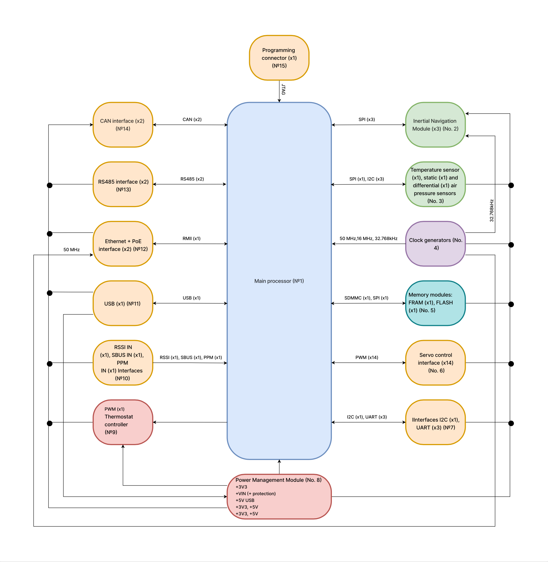
Figure 1. Block Diagram of the Flight Controller
UNIVERSAL FLIGHT CONTROLLER
TECHNICAL PRODUCT PASSPORT
Registration No.: N/A
Effective from «___» ________ 2025
Заводський №: SFC-25F02B-CHN-00864
Factory No.: SFC-1
When transferring the product to another owner, this passport must accompany the product.
2025
TABLE OF CONTENTS
Revision |
Date |
Description of Changes |
rev. A |
01.01.2024 |
Initial version |
rev. B |
01.01.2025 |
Typo corrections in Section X |
The universal flight controller (hereinafter referred to as the "flight controller") is intended for controlling aerial, ground, and surface unmanned vehicles.
It provides reliable control and navigation of unmanned platforms under demanding operating conditions.
The flight controller is delivered in the configuration specified in Table 1:
Table 1 – Delivery Set
№ |
Item |
Qantity |
1 |
Flight controller |
1 |
2 |
Connectors with pre-attached wires |
12 |
3 |
Packaging box |
1 |
4 |
Aluminum enclosure |
1* |
* - The enclosure is included only in the extended configuration and is not supplied with the basic flight controller kit.
The main components of the flight controller are listed in Table 2:
Table 2 – Core Components of the Flight Controller
№ |
Type |
Model |
Note |
1 |
Processor |
STM32H743 |
|
2 |
IMU №1 |
ADIS16470 |
|
3 |
IMU №2 |
ICM45686 |
|
4 |
IMU №3 |
BMI088 |
|
5 |
Magnetometer |
MMC5983MA |
|
6 |
Static air pressure sensor |
MS5611 |
|
7 |
Differential air pressure sensor |
5525DSO-B001DS |
|
8 |
Temperature sensor №1 |
TMP117 |
|
9 |
Temperature sensor №2 |
TMP390 |
Autonomous |
10 |
Memory (FRAM) |
MB85RS256 |
|
12 |
External watchdog timer / power voltage monitor |
CAT823 |
Autonomous |
The main interfaces of the flight controller are listed in Table 3:
Table 3 – Main Interfaces of the Flight Controller
№ |
Type |
Parameters |
Note |
1 |
1x Ethernet |
10/100 Mbit/s |
With Passive PoE support (8–50 V) |
2 |
2x CAN FD |
1 Mbit/s, 5 V |
Galvanically isolated (5000 V) |
3 |
2x RS-485 |
16 Mbit/s, 5 |
Galvanically isolated (3500 V) |
4 |
1x SBUS/PPM/DSM |
0…3.3V |
ESD protection + buffer |
5 |
1x RSSI |
0…3.3V |
ESD protection |
6 |
14x PWM |
0…3.3V |
ESD protection + buffer |
7 |
1x I2C |
400kHz, 0…3.3V |
ESD protection + re-driver |
8 |
1x USB Type-C |
USB FS |
For setup, firmware flashing, or debug power supply |
9 |
1x ARM JTAG |
— |
Standard full-size ARM JTAG |
10 |
1x Micro SD |
— |
ESD protection + power switch |
Controller Interface Connections (Tables 4 – 13):
Table 4 – Ethernet/PoE interface Connection
Ethertnet/PoE |
|||
№ |
Name |
Type |
Note |
1 |
RX+ |
Input |
|
2 |
RX- |
Input |
|
3 |
TX+ |
Output |
|
4 |
TX- |
Output |
|
5 |
VIN+ |
Power |
8–50V |
6 |
VIN+ |
Power |
8–50V |
7 |
GND |
Power |
|
8 |
GND |
Power |
|
Table 5 – SBUS/PPM/DSM/RSSI Interfaces Connection
SBUS/PPM/DSM (RC IN/ RSSI PWM) |
|||
№ |
Name |
Type |
Note |
1 |
+5V OUT |
Power |
|
2 |
RSSI IN |
Input |
|
3 |
SBUS/DSMX |
Input |
|
4 |
PPM IN |
Input |
|
5 |
GND |
Power |
|
Table 6 – I2C Interface Connection
I2C |
|||
№ |
Name |
Type |
Note |
1 |
+5V OUT |
Power |
|
2 |
I2C1 SCL |
In/Out |
|
3 |
I2C1 SDA |
In/Out |
|
4 |
GND |
Ground (Input) |
|
Table 7 – CAN Interface (№1 and №2)
CAN №1, CAN №2 |
|||
№ |
Name |
Type |
Note |
1 |
VIN |
Power |
Optional external power (8–50 V) |
2 |
CAN1 H |
In/Out |
|
3 |
CAN1 L |
In/Out |
|
4 |
GND |
Input |
|
Table 8 – RS-485 Interface (№1 and №2)
RS-485 №1, RS-485 №2 (galvanically unleashed) |
|||
№ |
Name |
Type |
Note |
1 |
VIN |
Power |
Optional external power (8–50 V) |
2 |
RS-485 V |
In/Out |
|
3 |
RS-485 A |
In/Out |
|
4 |
GND |
Input |
|
Table 9 – USART Interface (№1, №2, №3)
SBUS/PPM/DSM (RC IN/ RSSI PWM) |
|||
№ |
Name |
Type |
Note |
1 |
+5V OUT |
Power |
|
2 |
USART TX |
In/Out |
|
3 |
USART RX |
In/Out |
|
4 |
USART CTS |
In/Out |
|
5 |
USART RTS |
In/Out |
|
6 |
GND |
Power |
|
Table 10 – Main Power Input
PWR IN |
|||
№ |
Name |
Type |
Note |
1 |
VIN |
Power |
External power input (8–50 V) |
2 |
VIN |
Power |
External power input (8–50 V) |
3 |
GND |
Power |
|
4 |
GND |
Power |
|
Table 11 – PWM/GPIO Interface
PWM/GPIO |
|||
№ |
Name |
Type |
Note |
1 |
PWM1 |
In/Out |
|
2 |
PWM2 |
In/Out |
|
3 |
PWM3 |
In/Out |
|
4 |
PWM4 |
In/Out |
|
5 |
PWM5 |
In/Out |
|
6 |
PWM6 |
In/Out |
|
7 |
PWM7 |
In/Out |
|
8 |
PWM8 |
In/Out |
|
9 |
PWM9 |
In/Out |
|
10 |
PWM10 |
In/Out |
|
11 |
PWM11 |
In/Out |
|
12 |
PWM12 |
In/Out |
|
13 |
PWM13 |
In/Out |
|
14 |
PWM14 |
In/Out |
|
15 |
GND |
Power |
|
Table 12 – ARM JTAG Interface (20 pin)
ARM JTAG (20 pin) |
|||
№ |
Name |
Type |
Note |
1 |
VTref |
Power |
|
2 |
NC |
— |
Not used |
3 |
nTRST |
In/Out |
|
4 |
GND |
Power |
|
5 |
TDI |
In/Out |
|
6 |
GND |
Power |
|
7 |
TMS |
In/Out |
|
8 |
GND |
Power |
|
9 |
TCK |
In/Out |
|
10 |
GND |
Power |
|
11 |
RTCK |
In/Out |
|
12 |
GND |
Power |
|
13 |
TDO |
In/Out |
|
14 |
GND |
Power |
|
15 |
nRESET |
In/Out |
|
16 |
GND |
Power |
|
17 |
DBGRQ |
In/Out |
|
18 |
GND |
Power |
|
19 |
+5V IN |
Power |
|
20 |
GND |
Power |
|
Main technical specification of Flight controller is displayed in Table 13:
Table 13 – Technical Specifications
№ |
Characteristic |
Unit |
Measurement Conditions |
Value |
1 |
Supply voltage (including PoE input) |
V |
8–50 |
|
2 |
Current consumption |
А |
V = 12 М |
0.1±0.05 |
3 |
Power consumption |
W |
1.5 |
|
4 |
Gyroscope zero bias drift |
°/год |
T = 25 °С |
8.0 |
5 |
Gyroscope angle random walk |
°/√h |
0.3 |
|
6 |
Gyroscope bandwidth |
Hz |
550.0 |
|
7 |
Accelerometer offset instability |
μg |
13.0 |
|
8 |
Accelerometer measurement range |
g |
±40 |
|
9 |
Relative error of differential airspeed sensor |
% |
±0.25 |
|
10 |
Absolute error of static air pressure sensor |
mBar |
±2.5 |
|
11 |
Absolute resolution of static air pressure sensor |
mBar(m) |
0.012 (~0.1) |
|
12 |
Absolute temperature measurement error |
°С |
±0.1 |
|
13 |
Moisture protection |
IP |
IP64 or better |
|
14 |
Operating temperature range |
°С |
-55…+85 |
|
15 |
Main board dimensions |
mm |
170*85 |
|
16 |
Main board weight |
g |
84 |
|
17 |
Mean total lifespan |
h |
TBD |
Figure 1. Block Diagram of the Flight Controller
The flight controller (see Fig. 1) consists of the following modules:
The flight controller must be operated according to the requirements and conditions specified in this technical passport. Exceeding operational limits is not permitted.
The controller must be stored in an individual box and antistatic bag, in a dry, heated, and clean environment with a temperature from +5 to +40 °C and relative humidity not exceeding 80%.
The primary controlled parameters are listed in Table 14:
Table 14 – Controlled Parameters
№ |
Characteristic |
Unit |
Measurement Conditions |
Acceptable Range |
Inspection Result |
1 |
Supply voltage, V |
V |
8V, 12V, 50ВV |
8..50 |
+ |
2 |
Standby current, I |
А |
V = 12 V |
0.05-0.2 |
+ |
3 |
Absolute heater current |
TBD |
|||
4 |
Relative data loss overUSART |
% |
Test packet size - 512 bits, transfer rate - 115200 baud, 3 retries |
Not allowed |
+ |
5 |
Relative data loss over RS-485 |
+ |
|||
6 |
Relative data loss over CAN |
+ |
|||
7 |
Relative data loss over PPM |
+ |
|||
8 |
Relative data loss over SBUS |
+ |
Table 14 – Continued
9 |
Relative value of data loss when receiving via I2C port |
% |
Test packet size - 512 bits, transfer rate - 115200 baud, 3 retries. |
Not allowed |
+ |
10 |
Permissible relative error of RSSI level measurement |
< 3 |
+ |
||
11 |
Absolute latency (ping) over Ethernet |
ms |
< 50 |
+ |
|
12 |
Relative packet loss over Ethernet |
% |
100 packets of 64-bit length, sent over a local test network. |
< 1 |
+ |
13 |
Permissible relative error in servo control signal frequency, f |
V = 12 V, f = 50 HZ |
< 10 |
+ |
|
14 |
Permissible relative error in servo signal duty cycle, T |
V = 12 V, T = 1..2 ms. |
< 1 |
+ |
|
15 |
Number of non-operational sensors |
pcs |
All permissible operating conditions |
Not allowed |
+ |
Based on quality control results, the flight controller is deemed fit for operation.
Table 15 – onboard sensors controlled
| ADIS16470 | + |
| ICM45686 | + |
| BMI088 | + |
| SDMMC | + |
| Ramtron | + |
| LAN8720 | + |
| BMM350 | + |
| TMP117 | + |
| MS5611 | + |